This project is a high-speed CAN-Bus datalogger and >10Hz GPS for the BMW Z4 E85. It integrates into the onboard network and feeds data to RaceChrono over Bluetooth Low Energy (BLE).
- Gear indicator
- Bluetooth security
- High-speed GPS module
- Upload 3d printed enclosure .stl files and pictures
- Update rate improvements
- Merge CAN messages?
- XY-Axis acceleration data
- Formulas/decoding needs to be fixed
- ASL ESP32-CAN-X2
- ASL GPS Add-On
- Tulay's Wire Werks E46 CAN-Bus Plug and Play Adapter
- 3D printed enclosure (SLS nylon)
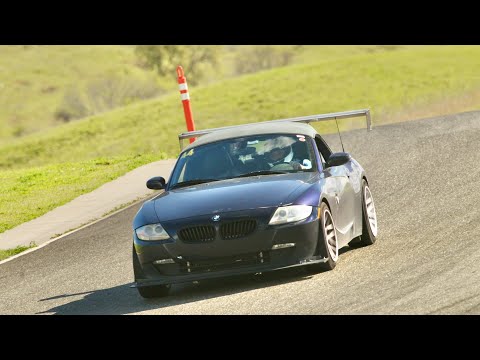
CAN data logger in action at Thunderhill West.

GPS module in action on a Yamaha R6 at Thuderhill East.


GPS module on the back of a Yamaha R6. No CAN input, obviously.
To achieve high CAN message throughput, the following things should be considered, roughly in order of importance:
- Ensure that there are free BLE transmit buffer available before sending (
esp_ble_get_cur_sendable_packets_num) - Set the connection intervals low on the server side (
esp_ble_gap_update_conn_params) - Request HIGH connection priority on the client side
- Choose 2M BLE PHY over 1M or CODED PHY
- Set BLE MTU higher than message size + 4
- Run freeRTOS CAN and BLE tasks with higher than 0 (IDLE) priority
- Use a fast CAN ARBID filter function
- Set the TX power to a high enough setting, depending on distance to phone
- Filter out uninteresting CAN ARBIDs in hardware
The traction and stability control module (DSC/ASC) in the Z4 comes with a 2D accleration sensor. Its data is transmitted over the CAN bus as part of the 0x1F3/499 message. While the specific fields/bytes containing the X and Y acceleration data are known, the exact conversion formulae are not. The following is my attempt at parsing the data experimentally, based on traces recorded in a controlled environment (a parking lot) and correlating the data with the accelerometer in my phone.
8 byte ASC3 CAN payload:
    A  B  C  D  E  F  G  H
0x 00 00 00 00 00 00 00 00

Longitudinal (Y axis, forward/backward, in m/s^2): ((((E & 0x03) << 8) | D) - 512) / 32.

Lateral (X axis, sideways, in m/s^2): (((F << 2) | ((E & 0xC0) >> 6)) - 512) / 20.

Reference: MS43 Wiki CAN ASC3
Note: this section is outdated. There is an API for setting the connection interval on the server side.
The BLE stack operates on two connection interval values (min, max), which
effectively determine the maximum possible update rate for CAN-bus messages
transmitted from the ESP32 device to the phone. While we can set the preferred
values on the server side with pAdvertising->setMinPreferred(0x06);, it's the
client (phone) which ultimately chooses the values. By default, my Android Pixel
4 seems to pick a balanced value resulting in a update rate of ~30-40 Hz. Apps
can explicitly request a priority for a given connection docs, picking between 4 presets.
In my experiments I used the nRF Connect app to both log and set BLE parameters. When following these steps, I could significantly increase the observed CAN message rate:
- Enable Bluetooth
- Open nRF Connect app and connect to data logger
- From drop-down, open "Request connection priority" and pick
HIGH - Confirm change in logs
- Open Racechrono
- Start new recoding session
- Open sensor menu
^and confirm "Bluetooth LE CAN-bus" update rate
Here are the different rates observed with different settings:
| Connection Prio | Data Rate [Hz] |
|---|---|
| default | ~45 |
| HIGH | >60 |
| BALANCED | ~45 |
| LOW_POWER | 7 |