DEPRECATION NOTICE: This repository, along with my others, is being migrated to Codeberg. I can be found at https://codeberg.org/fishd
I have a small stack of computers at home for work-related testing. I work with build automation so I need access to physical equipment in order to properly test as virtualisation is handy, but not 100% accurate when it comes to OS build and configuration (thinking hardware issues, kernel modules, that sort of thing).
My small stack is connected on a separate VLAN, and uses a multi-port KVM switch to connect 4 devices to a single screen, keyboard and mouse. This is all great, if I'm at home. I obviously can't take this with me, so if I need to travel for any reason, I wanted to be able to access my lab.
Enter the PiKVM.
This is a great piece of equipment.. but here in the UK it's a little on the expensive side for the hobbyist, and rarely in stock with the offical suppliers. There are alternative version (from Geekworm) but I wasn't sure of the quality and getting started with this setup required very little investment (I already had a Pi4 so just needed the HDMI-CSI bridge originally).
I thought I'd document my configuration and setup here, in case anyone finds it useful or I need to revisit it later. I found all of this information online on a number of websites, so I'm collating here for convenience.
- Raspberry Pi 4 (2Gb model is sufficient)
- HDMI - CSI bridge
90mm FPC connector- USB C Power splitter
- I2C OLED Screen
- Case
- Case screws
- 40mm PWM 3-pin fan
- Short USB-C male2male cable (for inside the PiKVM case)
- USB-C male to USB-A male (For connecting to the target device)
- USB-A male to USB-A micro male (optional, for connecting to a multi-port KVM)
- Multi-port KVM switch (optional, for controlling multiple devices)
- Smart Power Strip (optional, in place of ATX controls, can use this to restart Mini-PCs)
- Cables for connecting the OLED display (I used GPIO cables I had lying around)
- SD Card (I used a 32Gb card to allow it to hold several ISO images)

The OLED screen came bare, so I soldered the 4-pin connector so I could use the female to female GPIO cables. In hindsight I'd use right-angle pins on the OLED screen so it doesn't foul the internal cabling.
EDIT: I relented and added the right angle connector. This worked much better.
Connect the OLED display to the Raspberry Pi:
- GND - Pin 9
- VCC - Pin 1
- SDA - Pin 3
- SCL - Pin 5
/i/820311/products/2020-12-10T10%3A16%3A20.202Z-USB-C_PWR%20Splitter5V-2.jpg?1607566597)
You can power the Raspberry Pi directly from your host device, using a cable plugged into the power/OTG port on the Raspberry Pi... however if your host device loses power for some reason, then your PiKVM will also lose power... not what you might want.
If you power the Pi separately, but then connect a USB cable to your host device separately, then you might get power passed to the Raspberry Pi down the USB port and this could damage your Pi. The easiest way to avoid this is with a USB-C power splitter. This takes two inputs, one data and one power, and then passes them both on safely to your Pi power/OTG port by stripping the power lines from your data USB connection.
There's not a lot of room in the case and the distance from the USB-C port on the Pi to the power splitter isn't very far, so you need a really short, flexible cable. I struggled to find anything really short, so a 10cm cable had to work. I removed the braided outer with a sharp knife and I also removed some of the plastic strain relief to make the connectors shorter. Be careful here. The extra protection shouldn't be needed as the cable is inside the case, and with these parts removed, it fits a lot easier. Connect one end to the Raspberry Pi USB C port (power/OTG port) and the other end to the internal port for the USB-C power splitter.
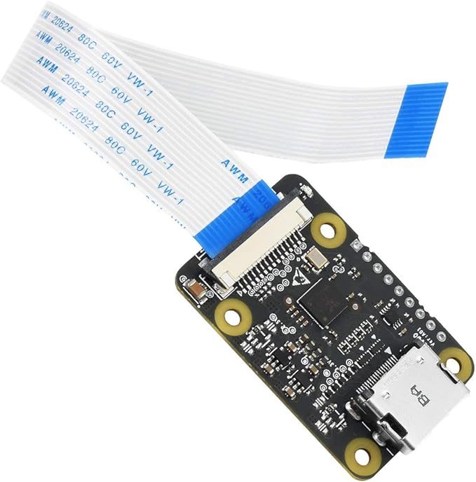
Originally I used the Geekworm HDMI-CSI bridge and it worked very well, however it doesn't physically fit into the case I had 3d printed. So, instead I ordered a new Waveshare bridge and this works and fits just fine... although the cable is a bit long. Fit as per the instructions.
EDIT: I see thepihut do 50mm or 100mm FPC cables (instead of the stock 150mm one) so I might try these.
FURTHER EDIT: So, I tried a 50mm FPC for this aaaaaannnndddd.... it isn't long enough. 90mm version on it's way.
ADDITIONAL FURTHER EDIT: 90mm version works perfectly, it's still a bit too long but better than the 150mm version
EVEN MORE EDITS: Not sure what happened but my apologies, the 90MM FPC I linked to does NOT work. The CSI bridge requires an FPC cable that has connectors on opposite sides of the cable and that 90mm one has them on the same side. This prevented my Pi from booting, so not sure how I tested that. I put the original 150mm cable back in for now.

I had the case above 3D printed by a service in the UK (SurfaceScan.co.uk), I chose to use PETG rather than PLA to give it a little extra heat resistance with a layer thickness of 200.0 µm and 50% infill. Later I will learn what this means.
Assembling the items into the case takes a bit of doing as it's a snug fit. Try to keep the cables short enough if you can to increase airflow and make the likelyhood of trapping anything less.
Add the case fan (as below), then slot each of the components into the case in their appropriate slots. The OLED screen might give you some trouble and try to fall out of it's place (again, might be easier with right-angled connectors?). Maybe a small amount of blu-tack or sugaru would help to hold it. Once the spaghetti of wires is tamed, push the two pieces together and gently screw in the case screws. These will be tight, go gently to avoid cracking the case. There are no inserts in this, so repeated opening of the case will cause it to loosen.

Add the fan to the case using the supplied nuts and bolts (shorter bolts would be ideal but they didn't foul anything). Wire the pins to the Raspberry Pi as below:
- Red - Pin 4
- Black - Pin 6
- Blue - Pin 32
EDIT: I replaced the stock M3 x 16 silver screws that came with the fans with M3 x 12 black screws, these do not protrude from the fan shroud so make it a bit easier inside for cabling.
- Connect the Pi to your network using an ethernet cable and the regular Pi ethernet jack (you can use WiFi, but ethernet is faster and more stable)
- Connect an HDMI cable from your device (or the output of the HDMI KVM if you're using one) to the input of the HDMI-CSI bridge
- Connect a USB-A male to USB-C male cable to a USB port on your host device (or the front USB port of the HDMI KVM if you're using one) to the DATA port on the USB-C power splitter
- (Optional) Connect the USB-A male to USB-A Micro cable between a USB 2 port on your Pi and the OTG port on the HDMI KVM
- Finally, connect the USB-C power supply to the POWER port of the USB-C power splitter. This will power up the device
First, grab the DIY V2 image from the PiKVM website (https://docs.pikvm.org/flashing_os/). Flash this to your SD card using something like Raspberry Pi Imager or Etcher.
Then follow the First Steps guide from the PiKVM website, this will get the basics of your device up and running.
Important
BE SURE TO CHANGE YOUR PASSWORDS!
To get the OLED screen working, we need to change a couple of things.
- Login to your PiKVM either via the website and then the console option, or via SSH if you've enabled it
- Change to root using:
su root - Change the filesystem to read-write mode with the command:
rw - As per the instructions at this site I added
dtparam=i2c_arm=onon a new line within/boot/config.txt - I also added
i2c-devto a new line within/etc/modules-load.d/kvmd.conf - (Optional) If you need to rotate the output of the OLED, you can do the following:
mkdir -p /etc/systemd/system/kvmd-oled.service.d-
echo '[Service]
ExecStart=
ExecStart=/usr/bin/kvmd-oled --height=32 --clear-on-exit --rotate=2' >> /etc/systemd/system/kvmd-oled.service.d/override.conf
- Enable the display service by running:
systemctl enable --now kvmd-oled kvmd-oled-reboot kvmd-oled-shutdown(ignore any errors, it will work after a reboot) - Switch to read-only mode using the command:
ro - Reboot the device
If you've wired the fan as I listed above, the below should be all you need to do. If you've used different GPIO pins or want different fan speeds or temperature thresholds, then the official documentation or this site might help.
- Login to your PiKVM either via the website and then the console option, or via SSH if you've enabled it
- Change to root using:
su root - Change the filesystem to read-write mode with the command:
rw - Run
systemctl enable --now kvmd-fan - Switch to read-only mode using the command:
ro
The webUI is likely showing your device name as localhost@localdomain. You can personalise this by:
- Login to your PiKVM either via the website and then the console option, or via SSH if you've enabled it
- Change to root using:
su root - Change the filesystem to read-write mode with the command:
rw - Edit the file:
nano /etc/kvmd/meta.yamland change the info afterhost:to reflect what you want - Switch to read-only mode using the command:
ro - Restart the service using
systemctl restart kvmd
If you're using the HDMI KVM to remote control multiple devices, and you have a supported KVM device, you can use the PiKVM menu to control the port selection remotely.
Instructions are found in the official documentation but basically:
- Login to your PiKVM either via the website and then the console option, or via SSH if you've enabled it
- Change to root using:
su root - Change the filesystem to read-write mode with the command:
rw - Edit the file:
nano /etc/kvmd/override.yamland include the following. Note the assumption that the KVM switch is present on/dev/ttyUSB0:kvmd: gpio: drivers: ez: type: ezcoo protocol: 2 device: /dev/ttyUSB0 scheme: ch0_led: driver: ez pin: 0 mode: input ch1_led: driver: ez pin: 1 mode: input ch2_led: driver: ez pin: 2 mode: input ch3_led: driver: ez pin: 3 mode: input ch0_button: driver: ez pin: 0 mode: output switch: false ch1_button: driver: ez pin: 1 mode: output switch: false ch2_button: driver: ez pin: 2 mode: output switch: false ch3_button: driver: ez pin: 3 mode: output switch: false view: table: - ["#Input 1", ch0_led, ch0_button] - ["#Input 2", ch1_led, ch1_button] - ["#Input 3", ch2_led, ch2_button] - ["#Input 4", ch3_led, ch3_button] - Switch to read-only mode using the command:
ro - Restart the service using
systemctl restart kvmd
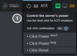
As I'm using a number of devices via the HDMI KVM, and my equipment doesn't support ATX controls, I've disabled them in the WebUI to avoid distractions. I found the instructions here but be sure to correctly format the resulting file. Incorrect edits will show unexpected results.
- Login to your PiKVM either via the website and then the console option, or via SSH if you've enabled it.
- Change to root using:
su root - Change the filesystem to read-write mode with the command:
rw - Edit the file:
nano /etc/kvmd/override.yamland include the following.kvmd: atx: type: disabled - Switch to read-only mode using the command:
ro - Restart the service using
systemctl restart kvmd
Warning
If you've already added the HDMI KVM switching above, do not add kvmd: a second time... the full file should look like this:
kvmd:
 gpio:
     drivers:
         ez:
             type: ezcoo
             protocol: 2
             device: /dev/ttyUSB0
     scheme:
         ch0_led:
             driver: ez
             pin: 0
             mode: input
         ch1_led:
             driver: ez
             pin: 1
             mode: input
         ch2_led:
             driver: ez
             pin: 2
             mode: input
         ch3_led:
             driver: ez
             pin: 3
             mode: input
         ch0_button:
             driver: ez
             pin: 0
             mode: output
             switch: false
         ch1_button:
             driver: ez
             pin: 1
             mode: output
             switch: false
         ch2_button:
             driver: ez
             pin: 2
             mode: output
             switch: false
         ch3_button:
             driver: ez
             pin: 3
             mode: output
             switch: false
     view:
         table:
             - ["#Input 1", ch0_led, ch0_button]
             - ["#Input 2", ch1_led, ch1_button]
             - ["#Input 3", ch2_led, ch2_button]
             - ["#Input 4", ch3_led, ch3_button]
atx:
type: disabled